OpenWRT AirPlay server on HP Thin Terminal

HP t5525 thin terminalI decided I needed an easier way of playing music on my old stereo in the workshop so it was time to see what could be done. I’m already quite a fan of Apple’s AirPlay protocol as it is very easy to use, however I wasn’t so keen on its proprietary nature. Fortunately this side of things has been solved and popular FOSS AirPlay server has been developed for Linux called ShairPlay.

The second part of the puzzle was to find some suitable hardware. I wanted something small and low power, preferably without moving part or dongles hanging of ports. Many folks use the Rasberry Pi and while I have  some lying about, the fact it uses PWM for the analogue audio output is a serious let down for music playback.

Diving deeper into the junk box I dug up an old HP t5525 thin terminal. This is really just a standard x86 PC crammed into a little box and designed for low power operation. It’s very well built and has no fans or other moving bits, and best of all it features far better audio performance than the Rasberry Pi. Here’s the basic specs:

  • VIA Eden 800MHz CPU
  • 128MB DDR RAM
  • 256MB IDE flash
  • VIA Rhine II Fast Ethernet
  • VIA AC’97 audio codec
  • 4x USB 2.0 ports
  • 1x serial, 1x parallel port

These thin terminals and later variants with AMD Sempron and Intel Atom CPUs can often be found dirt cheap on the second hand market (often for less than an RPi) and feature very low power consumption.

As far as software goes, OpenWRT supports x86 platforms and is designed for embedded platforms so it fits nicely with the limited amount of memory and storage on the thin terminal.

Image Download

If you just want to turn your VIA-based HP thin terminal into an AirPlay server with little fuss, just grab the image below.

Download OpenWRT 12.09 ‘Attitude Adjustment’ image with AirPlay support for VIA-based HP thin terminals.

This includes SSH, NTP, ShairPlay, ALSA, Avahi and kernel modules for the VIA Padlock crypto engine, VIA Rhine network and VIA AC’97 codec. Basic IPv6 support is included as ShairPlay seems to get upset without it. There’s also USB keyboard support which is handy if you don’t have a null modem cable lying about.

It’s very lean and I haven’t bothered to include much more than the bare necessities to administer the box and get AirPlay working. There is no web interface, wireless support or even drivers for any other brands of network interface. The root partition is 120MB so the while thing also fits onto the 128MB flash module fitted to the t5520 (Windows CE version of the t5525).

If you want additional functionality I suggest reading below to build an image with other utilities and packages.

OpenWRT Build Process

I’ve listed all the steps I took to build OpenWRT from scratch just in case it’s useful to anybody else.

This is easiest on a Linux distro. I suggest Linux Mint if you are new to that game and the instructions below are aimed at Ubuntu or Mint. If you use OS X then that should be fine; the OpenWRT wiki has a list of dependencies and you can install these easily via MacPorts or similar.

Install Dependencies

First install all the software we will require for obtaining and compiling the OpenWRT source:

sudo apt-get install build-essential gawk gcc-multilib git-core libncurses5-dev libxml-parser-perl subversion zlib1g-dev

Download the OpenWRT Source Tree

I used Attitude Adjustment so that’s what we will download here. Feel free to use a different version.

svn co svn://svn.openwrt.org/openwrt/branches/attitude_adjustment

Once this is complete you should find the entire source tree in the attitude_adjustment directory. The remaining commands assume you are working from this directory.

cd attitude_adjustment

Add ShairPlay Source

Mike Juni has forked an OpenWRT-specific version of ShairPlay. To include it, simply add the following line to feeds.conf.default:

src-git mikejuni git://github.com/mikejuni/OpenWRT-ShairPort;master

Now update the feeds:

scripts/feeds update -a
scripts/feeds install -a

Enable VIA AC’97 Kernel Modules

By default, OpenWRT doesn’t include modules for the VT8200 series AC’97 audio codec used in these old VIA HP thin terminals. That’s okay though as the modules we need are included in the mainline kernel, so it’s simply a matter of creating a suitable package definition to have OpenWRT include this.

Add the following lines to /kernel/modules/sound.mk. Note that the vt82xx modules depend on mpu401-uart.

define KernelPackage/sound-mpu401-uart
  TITLE:=MPU 401 UART support
  DEPENDS:=+kmod-sound-core
  KCONFIG:=CONFIG_SND_MPU401_UART
  FILES:=$(LINUX_DIR)/sound/drivers/mpu401/snd-mpu401-uart.ko
  AUTOLOAD:=$(call AutoLoad,36,snd-mpu401-uart)
  $(call AddDepends/sound)
endef

define KernelPackage/sound-mpu401-uart/description
  Routines for control of MPU-401 in UART mode
endef

$(eval $(call KernelPackage,sound-mpu401-uart))

define KernelPackage/sound-via82xx
  TITLE:=VIA VT82xx series AC97 Controller
  DEPENDS:=+kmod-ac97 +kmod-mpu401-uart
  KCONFIG:=CONFIG_SND_VIA82XX
  FILES:=$(LINUX_DIR)/sound/pci/snd-via82xx.ko
  AUTOLOAD:=$(call AutoLoad,37,snd-via82xx)
  $(call AddDepends/sound)
endef

define KernelPackage/sound-via82xx/description
 Support for the integrated AC97 sound device on motherboards
 with VIA chipsets.
endef

$(eval $(call KernelPackage,sound-via82xx))

Those trying to get sound support on older VIA C3 ITX boards may also find this useful.

Package Configuration

Now it’s time to configure the packages to be built in the OpenWRT image.

make menuconfig

This will start a menu driven interface similar to the one presented when selecting Linux kernel options.

OpenWRT configration menu

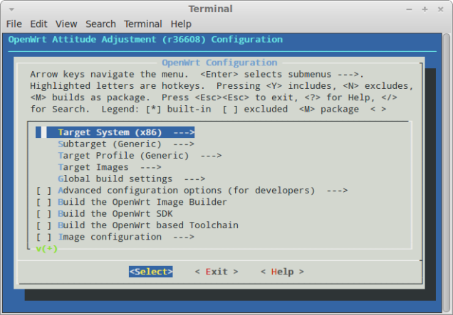
Here’s the options I chose; feel free to change these to suit your system. I set all to * to include them in the base image rather than as a package.

  • Target System: x86
  • Subtarget: Generic
  • Target Profile: Generic
  • Target Images
    • Root filesystem partition size: 120MB
  • IPv6
    • <*> 6scripts
  • Kernel Modules
    • Cryptographic API Modules
      • kmod-crypto-aes
      • kmod-crypto-hash
      • kmod-crypto-hw-padlock
    • Filesystems
      • kmod-fs-ext4
    • Libraries
      • kmod-lib-zlib
    • Network Devices
      • kmod-via-rhine
    • Sound Support
      • kmod-sound-mpu401-uart
      • kmod-sound-seq
      • kmod-sound-soc-ac97
      • kmod-sound-via82xx
    • USB Support
      • kmod-usb-hid
      • kmod-usb-storage
      • kmod-usb2
  • Network
    • IP Addresses and Names
      • avahi-autoipd
      • avahi-dnsconfd
    • SSH
      • openssh-client
      • openssh-server
    • Time Synchronization
      • ntpd
  • Libraries
    • Filesystem
      • libext2fs
    • SSL
      • libopenssl
    • alsalib
    • libavahi-client
    • libavahi-dbus-support
  • Utilities
    • alsa-utils
  • Sound
    • shairport

Exit the configuration menu and save changes when prompted.

Now go make some coffee while we compile; depending on the options chosen and the speed of your machine this can take over an hour.

make

If you are an optimisation freak check the make options on the OpenWRT wiki.

One the build process is finished the OpenWRT images can be found in bin/x86.

Installing onto the Thin Terminal

The easiest way is to copy the resulting image to a USB flash drive and boot off that. This process completely overwrites any existing content on the drive!

Plug the USB drive in and then locate the device node it uses:

dmesg | tail

Decompress the OpenWRT image and copy the OpenWRT image to the USB drive shown above (in this case /dev/sdc). It’s easiest to do this in one command and shown below:

gunzip -c bin/x86/openwrt-foo.img.gz | sudo dd of=/dev/sdc bs=1M

Once that’s complete, rescan the partitions with partprobe or unplug and reinsert the drive. If we mount the partitions now we can make some configuration changes before booting so you don’t need a keyboard or display on the thin terminal.

If it doesn’t mount automatically you will need to do this manually (once again replace /dev/sdc with your USB drive device):

sudo mkdir -p /mnt/openwrt/boot /mnt/openwrt/root
sudo mount /dev/sdc1 /mnt/openwrt/boot
sudo mount /dev/sdc2 /mnt/openwrt/root

Configuration

Root Password

You will need to change the root password before you can login via SSH. If you have mounted the USB stick simply do this with chroot (replace the path to the OpenWRT root partition if necessary):

chroot /mnt/openwrt/
passwd root

Enter a new password then type exit to leave the chroot.

Network

Network settings are configured by editing /etc/config/network. Here’s an example:

# Copyright (C) 2006 OpenWrt.org

config interface loopback
    option ifname   lo
    option proto    static
    option ipaddr   127.0.0.1
    option netmask  255.0.0.0

config interface lan
    option ifnam    eth0
    option type     bridge
    option proto    static
    option ipaddr   192.168.1.5
    option netmask  255.255.255.0
    option gateway  192.168.1.1
    option dns      192.168.1.1

AirPlay

You will need to change the name of the mixer control to use for the AirPlay volume control or ShairPlay will crash.

Edit etc/config/airplay and set the volume line to PCM. You can also change the display name that ShairPoint anncounces itself as, for example ‘Workshop’ or ‘Games Room’.

config airplay
        option bname 'Workshop'
        option initbuf 320
        option daemonize true
#       option port 5002
#       option password '123456'
        option pcm 'default'
        option ctl 'default'
        option volume 'PCM'

Boot Config

Because we will be initially booting off a USB stick we will need to change the target device in the GRUB configuration. This is held in the first partition on the USB stick (e.g. /mnt/openwrt/boot).

As an alternative, if you have a keyboard and display attached to your target machine you can press e in the GRUB boot menu and edit the line manually during each boot. This will save you needing to edit it again once it is copied to the internal flash.

Edit boot/grub/menu.1st and change /dev/sda2 to /dev/sdb2 (you can use command below to do this for you).

sed -i -e 's/sda/sdb/' boot/grub/menu.1st

Don’t forget to unmount the USB stick before unplugging it!

Installing on the Target System

Insert the USB stick and boot up the target machine. It should be accessible via SSH after a few moments. If not, plug in a screen and check for any errors.

The last remaining steps are to configure ALSA to actually output sound and then install the image onto the built-in IDE flash.
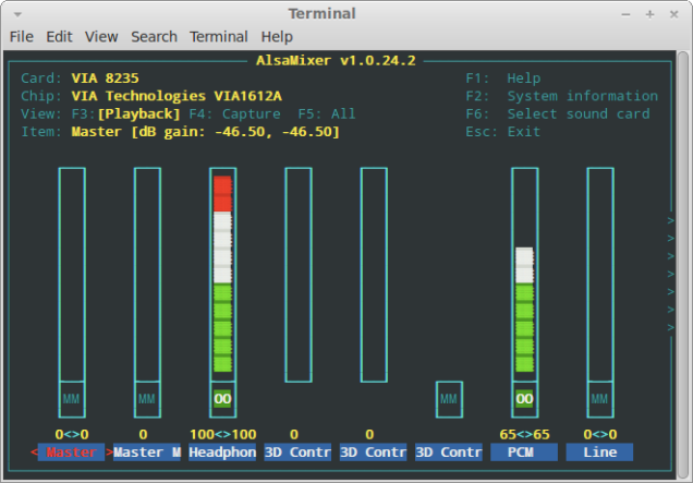
ALSA Configuration

Run alsamixer to set the output volume. Set Headphones to 100% and press M to unmute it. Do the same for PCM but I recommend setting the level to about 60%.

alsamixer

ALSA will forget this when the system is shut down so we need to make it persistent. First save the configuration as it is now:

alsactl -f /etc/alsa0.state store 0

Then to restore this on boot, save the following into /etc/init.d/alsa-cfg. Setting the order to 98 ensures that ALSA is set up correctly before ShairPlay starts.

#!/bin/sh /etc/rc.common
START=98
start() {                                 
    alsactl -f /etc/alsa0.state restore 0
}

Make it executable:

chmod +x /etc/init.d/alsa-cfg

Then enable it on boot:

/etc/init.d/alsa-cfg enable

Install on Internal Flash

From here simply block copy the USB stick onto the internal IDE flash:

dd if=/dev/sdb of=/dev/sda bs=1M

Once that’s complete, unplug the USB stick and reboot. Hopefully everything works as expected!

Bootnote

It’s getting late and I should really be doing homework so please accept my apologies if I’ve missed something!

I also found that image also works perfectly on the HP t5515 which is very similar but based on an 800MHz Transmeta Crusoe CPU. It draws even less power than the t5525 and appears to run happily off a 12v 1.5A power supply.

References

OpenWRT build documentation http://wiki.openwrt.org/doc/howto/build

ShairPort discussion https://forum.openwrt.org/viewtopic.php?id=29491

Vodafone Huawei K3772 3G modem support for TP-Link routers

TP-Link TL-MR3020 and Vodafone K3772 3G modemI recently purchased a Vodafone 3G USB modem and TP-Link TL-MR3020 3G router. After unboxing the modem I found that it was a Huawei K3772 which is unfortunately not compatible with TP-Link routers. After much searching around I contacted TP-Link support just for a laugh. Much to my surprise they responded within a few hours! Although most of the advice was just general troubleshooting, they provided a link to toolkit for Windows for producing a so-called ‘bin file’ for loading onto the router.

Following their somewhat quirky procedure worked and I now have a bin file that can be used to get these modems working. I submitted this back to the very helpful support crew at TP-Link and they appear to have handed it on to their engineers. Just how long it will take to appear on their website though is anyone’s guess.

If you would like to make your K3772 modem work with a TP-Link router using the simplest means possible, just grab the following file, unpack it and upload it to the router under the 3G modem settings page:

K3772 bin file

In the 3G/4G page (under Network), click Modem Settings:

TP-Link 3G modem settings page

If there are already any files loaded, delete them and restart the router before continuing. Click Add New… to upload the bin file you downloaded above.

TP-Link 3G modem bin file

Once the file is uploaded, restart the router and insert the 3G modem. You can check that it is working in the Status page. The LED on the modem should also illuminate in steady light blue colour.

TP-Link 3G status

If you would like a copy of the USB sniffer tool and the various scripts provided, it is available from TP-Link’s FTP server at ftp://ftp.tp-link.com/Temp/3G/TP-LINK_3G_USBSniffer_Guide_105.zip. Login is tplink and the password is wr641g@. I’m not sure how long that will last so I’ve also placed a mirror on Dropbox.

For those not in the know, the reason for all the mucking about is because many of these modems present themselves as virtual CD-ROM drives when connected so that they can automatically install drivers. Once the driver is installed it sends a command to the modem to switch it into modem mode.

Usb_modeswitch is a popular Linux tool created for this exact purpose, and unpacking the MR3020 firmware image with firmware_mod_kit reveals that it uses this very tool to set up modems that are connected. The bin file above simply seems to be some obfuscated instructions for usb_modeswtich.

Update: I’ve moved the modem file to a new storage provider as Dropbox kept blocking my public links due to excessive traffic.

Another update: If you are a little more technically inclined then I’d recommend installing OpenWRT instead (if your model is supported) and setting up the 3G modem as per the 3G instructions on the OpenWRT wiki. I can confirm that this works well for the K3772. Also, if you are thinking of buying a TL-MR3020 specifically for installing OpenWRT then don’t. Get the D-Link DIR-505 instead – it is based on the same platform (Atheros AR9330) but features double the flash and memory capacity (8MB and 64MB respectively) and the power supply is built-in.

Home telephone wiring in NZ

I had to perform some work on my home phone line including running new cable to a newly installed patch panel. I was suprised to notice that the existing cable had simply been twisted onto the incoming cable pair so this was quickly remedied.

Anyway, the incoming cable contained a single pair comprising of yellow and black wires. There had been several fingers in the pie and the cabling through the house was quite a mess, and figuring out the colour codes took a little bit of work, Here’s a guide for those living in an older NZ home who need to perform work on the phone line:

Cable Type Tip Ring
Incoming line Black Yellow
Existing house wiring Red White
Cat5 cable White(w/blue) Blue
Flexible phone leads Green Red

If you are still unsure, grab an LED and 10k resistor and connect the across the line. If it glows, the cathode is connected to tip and the anode to ring.

Connector Type Tip Ring
BS6312 (BT style) 5 2
RJ11 (6P6C) 4 3
RJ45 (8P8C) 5 4

HTC Wildfire S factory ROM update

A relative recently purchased a shiny new HTC Wildfire S from eking.co.nz. The phone itself is fantastic and I’ve had pretty good service from that site, however this particular Wildfire S turned up installed with a Chinese ROM, version 1.35.707. This version has loads of applications specific to China that cannot be removed and waste considerable space. I’m sure they are great for Chinese users but they are completely useless in New Zealand.

So the first step was to locate a suitable factory ROM image, so I decided on the European one. This took a bit of searching, but some ROMs are available from the following URLs. Note that the Wildfire S codename is Marvel (the original Wildfire codename is Buzz).

http://www.shipped-roms.com/index.php?category=android&model=Marvel
http://forum.xda-developers.com/showthread.php?t=1058089

I went for the Shipped ROMs version which is an official RUU installer from HTC. This contains a European ROM image. I’ve also made a copy available for download below:

HTC_Marvel_Europe_10.35.3029H_7.46.35.08_release_185724_signed.zip (use for SD and GoldCard updates)
10.35.3029H_7.46.35.08_release_185724_signed.exe
HTC Windows Drivers (install these when using Windows-based update)

ROM zip image MD5 sum:
0eb793740771a9d96ae4f5085c431516

Here’s the steps I tried to replace the factory firmware on the Wildfire S. While all three showed promise I ended up having to use the GoldCard method as the phone CID did not match that of the European firmware image, despite the fact that the images are signed by HTC.

If you purchased your phone from Eking and want to perform this I’d recommend going straight to attempt 3.

Note that I take no responsibility for any damage to your phone resulting from any of the instructions on this site!

The end result of the update was a fully functional phone with with an additional 60-70MB of internal storage freed up.

Attempt 1 – Official HTC Update Application (RUU)

My first attempt was to simply run the .exe file. Unfortunately this requires Windows but normally the process is fairly straightforward:

  1. Download and install HTC Sync.
  2. Ensure HTC Sync is not running or uninstall it and leave the HTC drivers installed.
  3. Power on the phone and enable USB debugging mode.
  4. Run the RUU application and follow the steps.

It did show that the update I was applying was actually a downgrade (v1.35.707 to v1.33.401) but it allowed me to proceed anyway. Unfortunately this failed after copying the image to the phone as it said the phone was the wrong type. After disconnecting the phone I powered it on and it still worked as before. Phew!

Attempt 2 – Flashing from the Boot Loader

The Wildfire S is like most HTC phones in that it can be forced to enter the boot loader by holding Volume Down when powering it on. From here it will look for a file named PG76IMG.zip on the root of SD card and attempt to load it if it exists, otherwise it will present the usual Android bootloader menu (text console with a picture of a three Androids at the bottom of the screen).

The neat thing about the Wildfire S supplied here is that it came already supplied in S-OFF mode.

The required zip file can be extracted from the HTC RUU application above. Don’t worry if the Windows built-in zip decompression doesn’t know how to open it; this does not mean that it is corrupt.

  1. Run the RUU application but leave it open at the welcome screen.
  2. Search your temp directory for a file called rom.zip and copy it to the SD card of the phone.
  3. Rename rom.zip to PG76IMG.zip.
  4. Close the RUU application.
  5. Unmount/safely eject the SD card (important!).
  6. Disable fast boot on the phone if it is enabled.
  7. Power off the phone and disconnect it from the USB port.
  8. Hold down the Volume Down button and power on the phone.
  9. When the bootloader screen appears it should locate the the ROM image file.
  10. Begin the update process when prompted.
  11. The phone will go through various update cycles and reboot itself several times.
  12. When the normal HTC splash screen appears it may take some time for the phone to finish booting; give it at least 10 minutes.

If you receive a message saying the update failed because of an incorrect CID (like I did) you will need to perform the GoldCard method below.

Attempt 3 – GoldCard Method

This method overrides the CID check on the phone.

  1. Format an SD card as FAT32 (if not already done).
  2. Boot the phone up with the SD card in it.
  3. Install GoldCard Helper from the Android Market and run it.
  4. Copy the CID.
  5. Visit http://psas.revskills.de/?q=goldcard and enter your email and CID. If you do this on the phone you can paste the CID from the GoldCard Helper app.
  6. When the email arrives it will have an attachment called goldcard.img. Save this somewhere on your computer.
  7. Connect the phone to the computer and mount the SD card on the computer.
  8. Copy the GoldCard image to the SD card.
    • If you use Linux, simply use dd to copy the GoldCard image onto the SD card. You will need to be root or use sudo for this. Also make sure you use the path to the SD card itself, not a partition on it. Mine was /dev/sdb but yours may differ.
      dd if=goldcard.img of=/dev/sdb bs=384
    • If you are stuck with Windows, download and install HxD Hex Editor.
    • Run HxD as Administrator (right-click and select Run as Administrator).
    • Go to Extras > Open Disk.
    • Select the physical SD device, not the logical one. Uncheck the read-only option and open it.
    • Open the goldcard.img file you received in another tab.
    • Select the entire contents of the GoldCard image and save it over the start of the SD device, address range 00000000 to 00000170. Save the changes and close HxD.
  9. Copy the ROM image to the root of the SD card and ensure it is named PG76IMG.zip.
  10. Unmount the SD card and disconnect the phone.
  11. Ensure the phone has fastboot disabled (change in Settings).
  12. Power off the phone.
  13. Hold down the Volume Down button and power it on.
  14. When the boot loader screen appears, release Volume Down.
  15. Confirm the update process when prompted.
  16. The phone will go through various update cycles and reboot itself several times.
  17. When the normal HTC splash screen appears it may take some time for the phone to finish booting; give it at least 10 minutes.
  18. Once the phone is back to normal operation, zero out the first 512 bytes of the SD card to destroy the GoldCard information.
    • In Linux simply run (as root), assuming your SD card is /dev/sdb:
      dd if=/dev/zero of=/dev/sdb bs=384 count=1
    • In Windows just use HxD to overwrite 00000000 through 00000170 with zeros and save.
  19. Enjoy!
  20. Make a donation to RevSkills for their awesome GoldCard generator.

Clarion CeNET – a first glance

I’m keen on reverse engineering at least some aspects of the Clarion CeNET bus in order to hook other gadgets to my car stereo. CeNET is a proprietary interconnect used by Clarion on many of their car audio products over the last ten years.

It uses a proprietary 13-pin square DIN style connector that is not available off the shelf. The pinout is shown below (this was taken from a Clarion service manual).

Electrically, CeNET appears to be a form of asymmetric serial bus. There is some discussion online that suggests a 38400 baud rate. The same person also says that it appears to use some form of encryption which may make it difficult to hack.

My experience with CeNET stereos is that the display will flash SYS or SYSTEM if the battery is disconnected or a CeNET device is inserted or removed. They do this until the stereo is powered on. Perhaps an encryption key is negotiated during that period?

On the hardware side, closer inspection reveals the bus consists of a transceiver IC (CA0008AM) connected to one of UARTs in the host devices microprocessor as shown in the simplified diagram below. Note that there are also some pull-down resistors on the Tx and Rx pins, as well as a 68 Ohm termination resistor across the Bus+ and Bus- pins. I’m unable to find data on the bus transceiver but I guess it’s possible that other generic ICs could be used here. The bus itself floats at 2.5v and swings +/- 200mV during signalling.

I have capture some data samples from a stereo connected to a EA-1251B iPod adapter that emulates a 6 disc changer. I haven’t yet studied them in detail but you can download the capture files below.

You will need to download Saleae Logic to view the capture files (it’s free). The cables were connected according to the colours in the diagram below:

In all captures I powered on the stereo from cold (no battery) immediately, then switched the unit on after about 3 flashes on the display (4-5 seconds). With the EA-1251 samples I switched from radio to the CD changer at about 7-9 seconds. From here the stereo waits for the iPod to wake up (it thinks the CD changer is loading) before it starts playing the first track of the first ‘disc’ (playlist) at about 14-15 seconds. The song then continues to play until the end of the capture.

Update: I’ve also grabbed a couple of samples of a TV tuner and display.

When the TV tuner is selected via the TV display it places the head unit into aux mode (it displays Aux on the screen). This could be a very useful hack; to make a ‘proper’ CeNet aux input. In the samples above, all units were powered up from cold (no battery) immediately after beginning the capture. The head unit is switched on at about 4 seconds, then there is a bit of wait for the display unit to boot up. Once this is done I’ve switched to the TV tuner at about 27 seconds. Shortly after (about 35 seconds) I switch back to the head unit’s internal FM radio.

It turns out trying to capture the bus pins was a waste of time as they normally float at 2.5V. I haven’t been able to look into that side of things any further as my only oscilliscope died before I could check it.

Hopefully somebody else finds this useful. I’ll keep working on it as I get time, and post any updates to the site if i come up with anything.

Vertical collapse on Storage System portable PC

I recently stumbled across a junked ‘Picollo’ portable PC made by Storage System Inc. This unit had a 66MHz 486 Overdrive processor and 10″ Sony Trinitron SVGA display and no doubt cost a fortune in its time.

Unfortunately the chassis had been partly gutted, missing the outer case and a variety of parts. The 10″ monitor still appeared to be salvageable however so I gave it a try.

After connecting everything as it appeared to go I connected a PC and powered on the display. Sadly the it was completely collapsed vertically, although I could make out enough detail in the thin line that appeared to be sure that it was otherwise functional.

The deflection is handled by the board mounted on top of the CRT. After fixing loads of dry joints around the horizontal output stage I decided to focus efforts around the vertical deflection stage.

This is based around an ST TDA1675A IC. I grabbed the datasheet for the IC and discovered that the circuit in the display was quite similar to the test circuit shown in the data sheet. The scope confirmed that the sync input was working, as well as the ramp generator. Unfortunately there was no output.

Google searching for the IC revealed many forum posts identifying this as a common cause of failure, and that it was also sensitive to failed components elsewhere in the vertical deflection circuit. Many people suggested replacing all of the surrounding capacitors and diodes as well as the IC just as a precaution.

TradeTech listed the IC as being on back order which was not ideal. In the mean time I though it would be worth attacking the other likely culprits in case the IC was still OK.

I replaced all of the electrolytics in the vertical stage as a matter of course but it didn’t fix the problem. I also identified a Zener diode (ZD201) with the marking ‘4A3’. After some research I found that this is in fact an HZ4A3, a 3.7V Zener. The closest I could get was a 3.6V 1N4729 so fitted one just in case. No difference.

There was also a standard 1N4004 rectifier diode (D207) mounted under the heatsink. I replaced this and it immediately fixed the problem! The weird part is that the diode appeared to check OK out of the circuit.

The horizontal yoke connector also had some discolouration on the plug due to heating because of a bad connection. I cleaned up the pins in the connector the the PCB header before reassembling it.

So now I have a dinky vintage 10″ Sony Trinitron SVGA display and just need to find a use for it! 🙂

HTC Desire and Belkin car charger

I noticed that my HTC Desire does not charge at full rate off my Belkin Micro USB car charger, despite it being the same rating as the original HTC wall charger (5v, 1A). It appears that the Desire obeys the somewhat recently introduced USB battery charging specification that states devices may draw up to 1.8A if the D+ and D- pins are connected by a resistance of no more than 200 Ohms.

This post shows how I modded my Belkin Micro USB car charger to charge my Desire at the full rate of almost 1A.

Getting the charger open is relatively easy; use a small flat screwdriver to pry the two halves apart. Note that the faceplate is attached to the side closest to the power LED. If the screwdriver takes too much effort you can use a vise to gently squeeze the sides along the seam to help break the seal.

Once the seal is broken the metal pin on the front will probably ping out and land somewhere awkward like under your workbench, so be prepared!

In inside looks quite tidy and simple:

Now solder a 180 Ohm resistor across pins 2 and 3 of the USB port.

To get it back together simply put a few drops of super glue along the seam. I used Selley’s Plastic Glue which is exceptionally good.

After this the battery status (Settings, About phone, Battery) shows as Charging (AC) instead of Charging (USB), indicating that the battery is now charging at full rate.

Hauppauge NOVA-S-Plus in Lucid

I’ve been using a Hauppauge NOVA-S-Plus DVB-S card for a while now with MythTV running on Ubuntu Hardy.

I recently upgraded to Lucid and had lots of difficulty getting the card to work with MythTV. All of the required kernel modules were loaded as expected (cx88xx, etc) and the device tree showed up as expected:

ls -l /dev/dvb/adapter0
total 0
crw-rw---- 1 root video 212, 1 2010-10-12 23:07 demux0
crw-rw---- 1 root video 212, 2 2010-10-12 23:07 dvr0
crw-rw---- 1 root video 212, 0 2010-10-12 23:07 frontend0
crw-rw---- 1 root video 212, 3 2010-10-12 23:07 net0

Testing dvbtune gave the following message:

dvbtune -f 1159000 -p H -s 22500000
FD 7: fd_dvr DEMUX DEVICE: : Device or resource busy

It turns out the fix is actually very simple, it’s just not very obvious or well advertised:

sudo apt-get install linux-firmware-nonfree

Apparently the firmware blobs have some legal restrictions regarding their distribution so they have been placed into a separate package as of Karmic.

Make sure you reboot after installing the firmware package.

Lucid gconf fail

This evening I encountered a weird problem when booting up Ubuntu 10.04. I simply had a black screen with a small error window saying:

There is a problem with the configuration server.
(/usr/lib/gconf2-4/gconf-sanity-check-2 exited with status 256)

Considering that I hadn’t knowingly changed anything last time I used the computer this seemed a little odd.

The following also appeared in /var/log/syslog:

Oct 13 22:05:34 hostname gnome-session[450]: WARNING: Error retrieving configuration key ‘/apps/gnome-session/options/auto_save_session’: Failed to contact configuration server; some possible causes are that you need to enable TCP/IP networking for ORBit, or you have stale NFS locks due to a system crash. See http://projects.gnome.org/gconf/ for information. (Details –  1: Could not send message to GConf daemon: Process /usr/lib/libgconf2-4/gconfd-2 received signal 6)

Fortunately the fix turned out to be easy; it’s simply a permission problem with /tmp. To fix it simply run:

sudo chmod 1777 /tmp