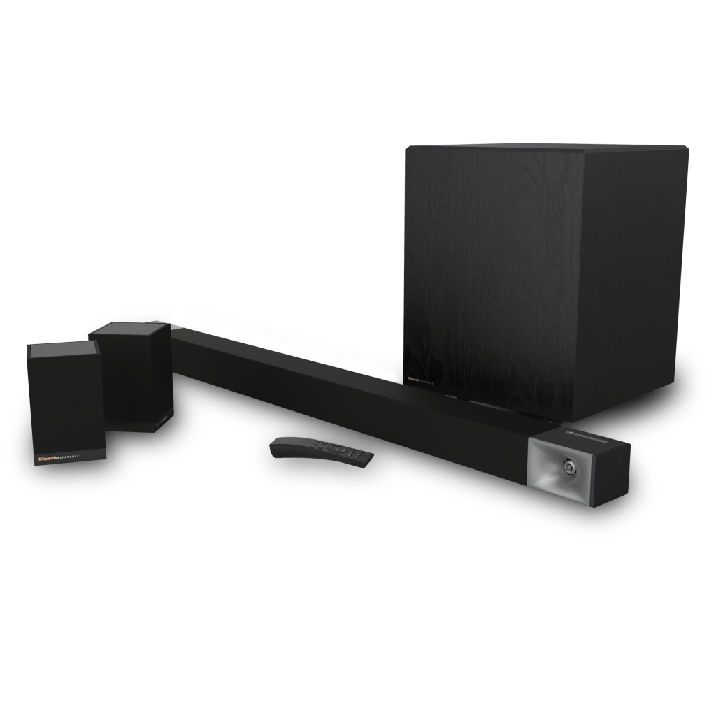
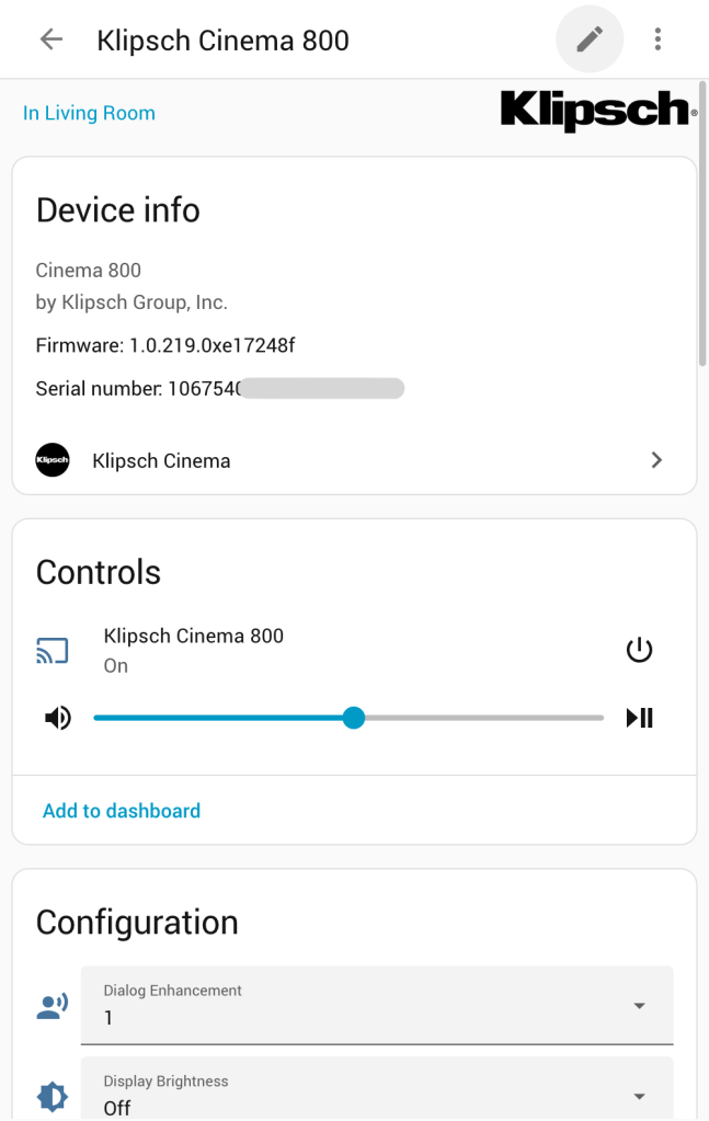
I recently created a rough but usable Home Assistant integration for the Klipsch Cinema 800 sound bar after reverse-engineering a firmware image and figuring out the unauthenticated web API it presents. The integration provides remote control for most of the sound bar functionality and is usually a bit more responsive than using the Klipsch Connect app.
It can be installed via HACS; simply search for the Klipsch Cinema integration. From there add a new device using the Klipsch Cinema integration and type in the IP of your sound bar.
I’m aware that this sound bar gets a bit of a mixed reception but I’ve found it very reliable to date and one of the better sounding models at the time I bought it.
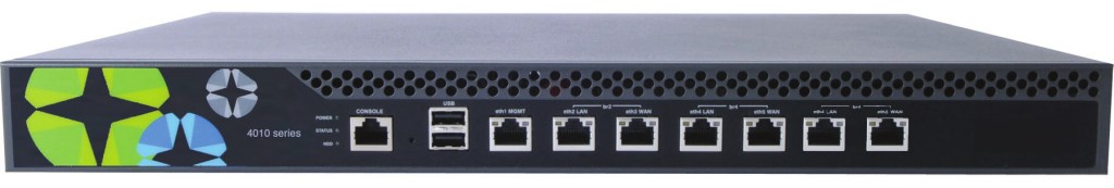
I wanted a quick and dirty route reflector for my home lab (more on that to come) and ended up repurposing an old Exinda 4010 WAN optimiser I had lying about. This unit is really just a re-branded Lanner FW-8756 (refer user manual), a generic x64-64 platform in a 1U rackmount case. It features six Intel gigabit Ethernet ports which was perfect for my intended use case.
It’s certainly not fancy; in the unit I have we find:
Intel Pentium E5300 CPU (dual core, x86-64, VT-x virtualisation support)
4GB RAM (expandable to 8GB by adding another DIMM although more might be possible).
500GB SATA HDD (replaceable – the bracket can also has holes to accommodate 2x 2.5″ HDDs but standoffs are required for the SATA cables to clear the motherboard).
100Mbps Realtek management port with PXE support
6x Intel 82574L Gigabit Ethernet ports
2x front panel USB 2.0 ports (plus an internal header for more ports)
In this case my intention was to run a more generic distro on it and install Free Range Routing. In my case I’ve opted for Ubuntu 20.04 LTS as it’s popular, well supported and super easy to build an image for. Pretty much any Linux distro will run on it though. Preparing a basic image to copy directly to headless devices like this is pretty straightforward, and much easier than the more common traditional method connecting a monitor to the motherboard headers and booting off an external drive.
This post will focus on getting this specific unit running as a generic Linux box, as well as explaining the process used for building an image that should work with minimal effort on a large range of similar devices.
I’ve also since tried this on a Watchguard M400 which is another rebranded Lanner product with a similiar design. The only major difference to the steps below being that there is no LAN bypass feature to worry about and the network interface name for the first Gigabit port is enp3s0.
Disable LAN Bypass
When I originally tried running a vanilla distro on the FW-8756 I couldn’t get the gigabit Ethernet ports to detect a link, despite everything looking normal in the OS.
It turns out the FW-8756 is one of several similar models with a “LAN bypass” feature. This consists of a series of bistable relays that can electrically connect each pair of network interfaces on the front panel, bypassing the NICs on the motherboard entirely. The bypass feature is software controllable via an I2C interface.
The FW-8756 platform was designed for use by WAN optimisers (as the Exinda 4010 is), so this bypass feature means that when it fails or is shut down the network link can continue to function as normal, albeit without the optimisation features provided by the unit.
This is all very clever except that it the default state is to go into bypass mode by default and isolate the ports from the internal NICs until switched over by a software included in the original firmware. When we install a generic OS there is no means out of the box to switch this over, and the LAN Bypass settings in the BIOS appeared to have no effect.
Rather than fudge a software fix, it appeared from the board layout that U93 next to the mini PCI slot was likely to be responsible for controlling this feature. There is an unmarked and undocumented jumper on the motherboard near this slot that appears to disable this bypass function permanently, making the network interfaces behave normally. There is an amber LED (LED12) near this jumper that appears to illuminate steadily when the LAN bypass function is operational, and flash when it is in bypass mode.
To make the network interfaces function with a generic Linux distro like Ubuntu you should permanently disable the LAN bypass feature entirely. Move the jumper so that it bridges pins 2-3 (closest to the front panel). The unit must be completely powered off (i.e. physically remove the power cord for at least five seconds) for this to apply.
If LED12 does not illuminate then the bypass feature is properly disabled and the LAN ports will function normally.
Serial Console and BIOS Reset
In the case of the Exinda 4010 I wasn’t able to get a serial console immediately so resorted to resetting the BIOS via the jumper next to the battery. After this I was able to get access to the console at 9600 8N1 using a common Cisco-style serial cable.
The instructions below assume the use of screen as a terminal emulator, although you can use your preferred application (e.g. minicom, HyperTerminal, PuTTY, etc). Ensure you use ANSI terminal mode so that the output displays correctly. Command line terminal emulators typically rely on the TERM environment variable for this, e.g:
TERM=ansi screen /dev/ttyUSB0 9600
When the device is first booted after a BIOS reset the machine will pause for input during POST, requiring F1 to be pressed to enter the BIOS setup. Several options exist:
Some terminal emulators will interpret F1 properly – just press the key and away you go.
Connecting a USB keyboard to the machine itself and pressing F1 also works as an alternative.
If your terminal emulator doesn’t interpret the F1 key, another option is to quit the terminal emulator and run the commands below from a shell. The first command sets the serial port to 9600 baud and the second sends an escape character followed by the letters OP which combine to simulate pressing F1.
To enter the BIOS setup on subsequent boots press the tab key during POST instead of F1.
In most cases (including if you flash the image I’ve described below) I’d recommend setting the following settings in the BIOS to improve serial access:
Advanced -> Remote Access:
Serial Port Mode: 115200 8, n, 1
Terminal Type: VT100
From this point on you should connect to the serial console at 115200 baud.
Quick Start
If you just want to use the thing and don’t care about making an image yourself, here are the basic steps:
Decompress and write the image directly to a disk: zcat ubuntu-focal_exinda4010_amd64.img.gz | sudo dd of=/dev/sdb bs=1M oflag=direct status=progress
Optionally grow the partition size and filesystem to fill the disk: sudo parted /dev/sdb resizepart 1 100% sudo e2fsck -f /dev/sdb1 sudo resize2fs /dev/sdb1
Insert the disk into the device and boot it up.
Access the device via serial or SSH.
Creating an Image From Scratch
If you would prefer to create an image from scratch rather than download a pre-made one you can do so using the following method.
As I’m opting for Ubuntu and using debootstrap to create the image, these steps will need to be run on a system running a Debian derivative of some type (including Ubuntu itself).
Install debootstrap on your system:
sudo apt install debootstrap
Now we need to decide on the storage media. You could either make a disk image file and perform all the operations in that, or do all the work directly on a disk.
Disk
If you opt for a disk then connect it to the system you are building the image on (e.g. via a USB adapter) and immediately check dmesg for the device node:
In the above example the disk is /dev/sdb but yours may vary slightly. If it is different to sdb then you will need to modify all of the commands in the examples below to suit.
Image File
As an alternative to directly connecting the disk, create a 4GB image file we can using the following command:
This generates a 4GB “sparse” (also known as thin provisioned) file; although ls will report it as 4GB in size, du will show the disk usage as the actual space used up by the file. This process saves writing out a large number of zeros to fill the file, although at the risk of filling the parent filesystem as the file is written to later if there is insufficient space available.
Now set up the image as a loop device so that we can treat it just like a normal block device (i.e. disk):
Note the output of the above command; this is the path to the loopback device (e.g. /dev/loop0).
From here use this path as the path to the disk for the remaining commands in this post. The rest of the process is exactly the same.
Partition and Format
The first step is to create a partition table, partition and format the disk, regardless of whether you opted for an image file or directly writing to disk. Don’t blindly copy and paste these commands – you will need to bear in mind the path to the disk or image file and use what is appropriate for your system.
sudo parted /dev/sdb mklabel msdos
Create a primary partition that fills the disk:
sudo parted /dev/sdb mkpart pri ext2 0% 100%
If you used a disk, the path to the new partition device is likely the same as the disk path with a 1 appended (e.g. /dev/sdb1). If you are using an image attached with a loopback device, the partition path will be the loop device appended with p1 (e.g. /dev/loop0p1). Now create an ext4 filesystem in the new partition:
sudo mkfs.ext4 /dev/sdb1
Mount the new partition to a location on your system. In many cases the /mnt directory is a good choice, unless you’ve already used it for something else in which case you can probably figure out how to make a suitable mount point of your own. 🙂
sudo mount /dev/sdb1 /mnt
Build the Image
Now use debootstrap to build a base operating system image. The two major arguments you need are:
Distro codename (e.g. focal for Ubuntu 20.04 LTS “Focal Fossa”).
Path to a mirror to use for downloading packages.
Consult your preferred distro documentation to find out what codenames and mirror locations to use. The command below will work for Ubuntu 20.04 from the New Zealand mirror. If you are not in New Zealand then you may wish to substitute nz. with your own country code, or remove it altogether for the primary Ubuntu mirror:
Once that’s done, mount the /dev tree inside the image so that the disk devices on your system are accessible while in the chroot:
sudo mount -o bind /dev /mnt/dev
Now chroot into the image to get a root shell. Note that we should set the locale to C to avoid warnings being thrown about locale mis-matches when running some commands. We can fix up locales later.
LANG=C sudo chroot /mnt
Temporarily mount /proc and /sys so the chroot environment looks like a normal root file system and other things work as expected:
mount -t proc proc /proc
mount -t sysfs sysfs /sys
Configure and Update the Image
Add an entry for the root filesystem to /etc/fstab (noting the disk path used by the blkid command should match the one you used in previous steps):
Clear out the package cache to reduce the image size a little:
apt clean
Add the following config to /etc/default/grub to enable the serial console, we well as disabling the existing quiet boot mode so that kernel messages are logged to the console:
Disable the GRUB OS prober – this prevents the GRUB update command from adding entries for operating systems on other disks in the host system:
rm /etc/grub.d/30_os-prober
Update GRUB config to apply the above changes and then write the GRUB bootloader to the disk. Note the disk path again – change this to suit your system if need be.
update-grub
grub-install /dev/sdb
Set the hostname (feel free to change this to anything you like):
echo exinda > /etc/hostname
Generate a basic network config for the management port (enp7s1). We can either use DHCP or set a static IP address – up to you! If you’d rather use the first gigabit network port then change enp7s1 to ens32 in the examples below. Other configurations are also possible.
DHCP Config
Run this command to generate network configuration to obtain an IP address via DHCP:
The final step is to make a group called admin (this enables sudo access out of the box in Ubuntu) and user account to log in with that is a member of this group. The third command sets the password for this user.
groupadd admin
useradd -s /bin/bash -m -d /home/user -G admin user
passwd user
Finish Up
That’s it! Exit the chroot, then unmount the filesystems before disconnecting the disk:
exit
sudo umount /mnt/{dev,proc,sys} /mnt
If you used an image file instead of writing directly to a disk there are a couple of extra steps. If you intend to compress the image for distribution then you can choose to zeroise any unused blocks from old files that were removed during patching to further improve compression – this almost halved the size of the compressed image in my case. This step is purely optional and a downside is that it will fill up a sparse image file with zeros causing it to take up the entire space on disk:
sudo zerofree /dev/loop0p1
Finally, if you are working on an image file then you should remove the loopback device attached to the image:
sudo losetup -d /dev/loop0
From here the drive can be installed directly into the Exinda appliance. If you opted for an image file then write this to a suitable disk and install that, e.g:
I recently had a case to install Windows Server 2016 on a Dell PowerEdge R630 server. Microsoft make the ISO images available for download on their website, however the Windows Server 2016 ISO clocks in at over 6GB. Actually getting the server to boot and install from this ISO image was surprisingly difficult:
It’s too large for a regular DVD-R disc, and I didn’t have any dual-layer discs on hand.
The ISO image contains a file (install.wim) that is greater than 4GB, so won’t fit on a FAT32 filesystem as created by tools such as Unetbootin.
There is a command in Windows (dism) to split a WIM file but hadn’t come across any Linux tools to date. Update: wimlib can do this and means you can probably do this on a legacy FAT filesystem after all!
It’s too large to fit into Dell vFlash which has a image size limit of 4GB (presumably as it uses FAT32 internally).
Tools that were known to work such as Rufus and the Microsoft USB imager only run in Windows, which I didn’t have handy.
The ISO mounting capability via the server iDRAC console actually worked, but was painfully slow (hours).
So I set about to find a way to make a bootable Windows USB stick when you’ve only got immediate access to a Linux box. This took a few attempts to get right but turns out to be relatively simple. I imagine this will also be perfectly doable on a Mac as well, with a few modified commands.
Process
Here’s the actual process to create a bootable Windows installer on a USB stick from a Windows installer ISO image for a UEFI system. This should work for any Windows version released over the last decade or so. Secure Boot must be disabled for this to work.
WARNING: This will erase any existing data on the USB stick!
Plug the USB stick in and run dmesg to see what identifier it gets:
[28959.294103] usb 4-1: new SuperSpeed Gen 1 USB device number 15 using xhci_hcd
[28959.319266] usb 4-1: New USB device found, idVendor=0781, idProduct=5581, bcdDevice= 1.00
[28959.319278] usb 4-1: New USB device strings: Mfr=1, Product=2, SerialNumber=3
[28959.319282] usb 4-1: Product: Ultra
[28959.319286] usb 4-1: Manufacturer: SanDisk
[28959.319290] usb 4-1: SerialNumber: 1234567890
[28959.321513] usb-storage 4-1:1.0: USB Mass Storage device detected
[28959.322014] scsi host7: usb-storage 4-1:1.0
[28960.347536] scsi 7:0:0:0: Direct-Access     SanDisk  Ultra            1.00 PQ: 0 ANSI: 6
[28960.348477] scsi 7:0:0:0: Attached scsi generic sg2 type 0
[28960.349336] sd 7:0:0:0: [sdb] 60063744 512-byte logical blocks: (30.8 GB/28.6 GiB)
[28960.350654] sd 7:0:0:0: [sdb] Write Protect is off
[28960.350664] sd 7:0:0:0: [sdb] Mode Sense: 43 00 00 00
[28960.351430] sd 7:0:0:0: [sdb] Write cache: disabled, read cache: enabled, doesn't support DPO or FUA
[28960.399678]  sdb: sdb1 sdb2
[28960.402932] sd 7:0:0:0: [sdb] Attached SCSI removable disk
In this case the disk shows up as sdb, so the device we’ll use for this exercise is /dev/sdb. Yours may vary depending on how many disks you have connected to the system so you will need to modify the remaining commands accordingly.
The first step is to create a new GPT partition table:
sudo parted /dev/sdb mklabel gpt
Create an exFAT partition for the Windows ISO contents. We’ll set the partition type as NTFS; that is correct for exFAT. For the sake of simplicity I suggest using 0% and 99% as the boundaries as the exFAT driver filesystem image is only 512k. It’s a quick hack that saves calculating partition sizes and also helps ensure that parted correctly block aligns the partitions.
We’ll also need to enable the msftdata flag on the partition and then format it with an exFAT filesystem:
sudo parted /dev/sdb mkpart winsetup ntfs 0% 99%
sudo parted /dev/sdb set 1 msftdata on
sudo mkfs.exfat -n winsetup /dev/sdb1
Mount the Windows ISO and the exFAT USB stick partition. I suggest making some temporary working directory for these:
mkdir -p /tmp/{iso,usb}
sudo mount ~/Downloads/Windows_Server_2016_Datacenter_EVAL_en-us_14393_refresh.iso /tmp/iso -o loop,ro
sudo mount /dev/sdb1 /tmp/usb
cp -r /tmp/iso/* /tmp/usb/
Now create a partition for the exFAT/NTFS driver, and set the msftdata flag on this partition as well:
sudo parted /dev/sdb mkpart uefi-ntfs 99% 100%
sudo parted /dev/sdb set 2 msftdata on
We don’t need to format this one, we’ll just copy the Rufus driver image directly to it:
Sometimes when deploying stuff in the lab with self-signed certificates I find myself quickly rebuilding VMs after making breaking changes. Normally that’s not a problem, except when Firefox is being used to access the rebuilt VM occasionally we might see this error:
Secure Connection Failed
An error occurred during a connection to 192.168.24.201. You are attempting to import a cert with the same issuer/serial as an existing cert, but that is not the same cert.
Error code: SEC_ERROR_REUSED_ISSUER_AND_SERIAL
The page you are trying to view cannot be shown because the authenticity of the received data could not be verified.
Please contact the website owners to inform them of this problem.
I often see this occur with Foreman where the default configuration relies on the Puppet CA for certificate issuing.
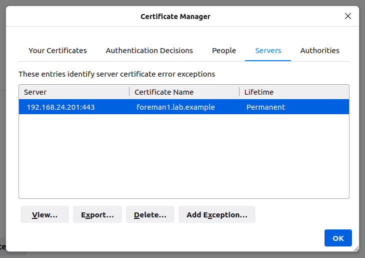
In theory you should be able to fix this by heading to Settings -> Privacy & Security -> View Certificates, selecting the Servers tab and then deleting the offending entry. In practice, however, this doesn’t often work.
Some forum posts suggest removing the entire certificate database. This works, but it’s a bit heavy handed as it clears out any other exceptions you may have saved in the past.
To fix this properly we need to use certutil as included with the Mozilla NSS tools. This command shouldn’t be confused with certutil.exe included with Windows, which is completely unrelated!
In install certutil on Ubuntu we need the libnss3-tools package:
sudo apt install libnss3-tools
In macOS, I recommend using Homebrew or MacPorts to install the nss package e.g:
brew install nss
Quit Firefox if it’s running. In theory it’s possible to do this in-place with SQL NSS databases but I’ve found it a bit hit and miss in practice.
First we need to figure out the Firefox profile directory. The configuration for this is usually in ~/.mozilla/firefox/profiles.ini(Linux) or ~/Library/Application Support/Firefox/profiles.ini (Mac).
Identify the Path to your profile directory, in this case
So in this case my profile directory would be ~/.mozilla/firefox/profiles/w6znk57b.default in Linux or ~/Library/Application Support/Firefox/Profiles/w6znk57b.default on Mac. Yours may vary slightly – just note that the Path entry is relative to the location of profiles.ini so you need to include any subdirectories in your commands. Note that the path is case sensitive.
From here we can use certutil to list the certificates (-L) in this store to find the offending entry. Modern versions of Firefox use the SQL NSS database, so we need to provide the location of the database in the form of sql:path.
A tip here – it might be useful to use grep to filter for the common name of the certificate used by the page throwing the error.
In this case the foreman1.lab.example entry is the offending one that we want to remove. To get rid of it we use the certutil delete command (-D) and specify the certificate nickname listed above after the -n argument. I recommend putting quotes around the nickname in case it includes spaces.
If certutil doesn’t return any messages then it’s likely to have worked. To verify we can simply run the list command again to check:
certutil -d sql:$HOME/.mozilla/firefox/profiles/w6znk57b.default -L
Certificate Nickname                                         Trust Attributes
                                                             SSL,S/MIME,JAR/XPI

DigiCert SHA2 Secure Server CA                               ,,
DigiCert TLS RSA SHA256 2020 CA1                             ,,
R3                                                           ,,
Amazon                                                       ,,
GTS CA 1O1                                                   ,,
At this point you should be able to reload the offending site and it should now work (although you will likely be prompted to accept the certificate again!).
If the above steps don’t work, try closing Firefox and repeating the delete command without the sql: prefix.
I’ve been using a VMware ESXi box as the foundation for a home lab for many years now, but without the benefit of the full (expensive!) vSphere/vCenter suite it’s a relatively tedious affair for managing anything beyond a tiny handful of virtual machines. I’ve recently begun using Vagrant for making bulk provisioning much faster, easier and more repeatable. It works well with VMware Fusion on the MacBook but I find the ESXi support a little lacking by comparison. It’s functional but has network configuration quirks and is very slow to provision VMs as it relies on copying the image to the ESXi host for every VM creation.
I recently had an attempt at interfacing Vagrant to libvirt/KVM/QEMU, the native virtualisation stack in Linux, and it’s a breath of fresh air! I’ve now replaced ESXi completely in favour of this setup.
Here’s a quick guide for anyone who is new to the process. While it would help to have basic familiarity with Vagrant, libvirt and Linux networking, I’ve tried to make this as easy as possible to get started.
I’m basing this example on Ubuntu 20.04 LTS. The same basic concepts apply to any Linux-based operating system, however you’ll need to adapt the instructions if you wish to use a different distro.
Networking Background
In the first instance I’ll attempt to explain some Linux networking basics to help provide some background for those relatively new to Linux virtualisation. VMware ESXi makes networking a fairly point-and-click affair; in Linux you’ll need to learn how to configure networking a bit more manually.
For the sake of keeping this article as simple as possible I won’t get into VLANs just yet; I’ll save that for a later post. In the example below I’ll be sharing the same network with the VMs and the host.
When using Linux virtualisation, the most common way to attach networks to virtual machines is to use bridges – these are essentially a software representation of a network switch (a switch is in fact a multi-port bridge!). This mimics the method that is most commonly done with VMware ESXi.
In the case of this post we’ll create a new bridge interface called br-mgmt. You can call it anything you like (within reason) but maintaining a naming convention helps to make interfaces easier to identify when you are managing the system. I often use the br- prefix followed by a short label for the function of the bridge. In this case I’ve used mgmt as this is will be the interface I use for accessing and managing the host.
Because I’ll be using this bridge on the same network as the one I’m accessing the host itself, we’ll need to ensure that:
The physical network interface of the host is attached to the bridge, and
The IP address used for accessing the host is attached to the bridge interface, not the physical interface.
We’ll cover this in the next section.
Network Setup
As I’m using Ubuntu 20.04 we’ll configure networking using Netplan. Although Netplan lacks a significant amount of advanced functionality, it’s relatively simple to set up and comes supplied out of the box. I don’t recommend you disable Netplan unless you are experienced enough to deal with networking via another means.
If you are using a different distro you will need to consult the distro documentation for instructions instead.
First find the interface name for the NIC in your machine using the ip address command; the exact name will depend on the hardware configuration of your machine:
ip address
1: lo: <LOOPBACK,UP,LOWER_UP> mtu 65536 qdisc noqueue state UNKNOWN group default qlen 1000
    link/loopback 00:00:00:00:00:00 brd 00:00:00:00:00:00
    inet 127.0.0.1/8 scope host lo
       valid_lft forever preferred_lft forever
    inet6 ::1/128 scope host
       valid_lft forever preferred_lft forever
2: eno1: <BROADCAST,MULTICAST,UP,LOWER_UP> mtu 1500 qdisc fq_codel master eno1 state UP group
    link/ether 54:52:00:d3:f5:eb brd ff:ff:ff:ff:ff:ff
    inet 192.168.10.7/24 brd 192.168.10.255 scope global dynamic noprefixroute eno1
       valid_lft 1227sec preferred_lft 1227sec
    inet6 fe80::1cf3:edff:fe8c:3ca3/64 scope link
       valid_lft forever preferred_lft forever
In this case the physical interface name is eno1 and it has the IP address 192.168.10.7. If the interface name on your own host is different then you will need to substitute it accordingly in the instructions below.
We’ll create a new Netplan configuration to:
Remove the IP address from the physical interface.
Disable DHCP on the physical interface so it doesn’t try to get an IP address automatically.
Create a new bridge called br-mgmt.
Attach the physical interface as a member of the br-mgmt bridge.
Assign an IP address via DHCP to the bridge.
Back up and remove any existing configuration from Netplan:
Log out and in to apply the group membership. At this point we should be all ready to go!
Vagrant Quick Start
Make a new directory for our project (e.g. lab1) and change into it:
mkdir lab1
cd lab1
We’ll also need the Vagrant libvirt plugin:
vagrant plugin install vagrant-libvirt
We need to create a Vagrantfile to define how our lab will look. In this case I’m going to create a lab with two VMs, both on the br-mgmt network with a fixed IP of our choosing. All will run Ubuntu 20.04 LTS.
Hostname
CPU Count
RAM (GB)
IP Address
vm1
2
3
192.168.10.201
vm2
1
1
192.168.10.202
vm3
1
2
192.168.10.203
Create a Vagrantfile to define some VMs using the template below. Note the custom network bridge to suit the bridge name we used in Netplan! The contents below should be saved as a file called Vagrantfile in the current working directory.
# Use libvirt as the default provider
ENV['VAGRANT_DEFAULT_PROVIDER'] = 'libvirt'

# Name of the bridge interface created in the steps above
bridge_iface = "br-mgmt"

# Define CPU count, memory (MB) and public IP addresses
# You can add any few or many lines as you like, assuming there is sufficient resource to run them!
nodes = {
  "vm1" => [2, 3072, '192.168.10.201'],
  "vm2" => [1, 1024, '192.168.10.202'],
  "vm3" => [1, 2048, '192.168.10.203'],
}

Vagrant.configure("2") do |config|
  # Use Ubuntu Focal image
  config.vm.box = "generic/ubuntu2004"


  # Apply config to each VM
  nodes.each do | (name, cfg) |
    numvcpus, memory, ipaddr = cfg

    config.vm.define name do |node|
      node.vm.hostname = name
      node.vm.network :public_network,
        :dev => bridge_iface,
        :mode => bridge",
        :type => "bridge",
        :ip => ipaddr

      node.vm.synced_folder('.', '/Vagrantfiles', type: 'rsync')

      node.vm.provider :libvirt do |v|
        v.memory = memory
        v.cpus = numvcpus
      end
    end
  end
end
Now to start the VMs run this command:
vagrant up
The first attempt might be a bit slow as the image will need to be downloaded and cached.
If you want to verify that the VMs are running you can use the virsh list command:
virsh list

 Id   Name               State
----------------------------------
 1    libvirt_vm1        running
 3    libvirt_vm2        running
 4    libvirt_vm3        running
To shut down VMs but retain their state:
vagrant halt
If you want to completely delete the VMs run the following command.
vagrant destroy
If you modify the configuration of any existing VMs in the Vagrantfile then you will need to destroy those VMs and rebuild then again using vagrant up.
To access a VM for administration, use vagrant ssh <hostname>, e.g:
vagrant ssh vm1
If you install any applications on the VMs then they should be accessible on the network via the IP addresses we set above.
Desktop App
If you are running this on a desktop machine then you can use the Virt Manager app to view and interact with the VMs. First ensure that it is installed:
sudo apt install virt-manager
From here you should be able to run the Virtual Machine Manager application from your desktop:
Conclusion
There we have it, a quick crash course in using Vagrant to drive libvirt! In coming posts I’ll describe a bit more about common tasks in libvirt and also using Vagrant and Ansible together to automatically configure the VMs after deployment, which is where the real power comes into this toolset!
I recently installed Ubuntu 20.04 “Focal Fossa” on an old desktop. My junk box has shrunk over the years so the only surplus graphics card I had on hand was an ancient Nvidia GeForce 210.
I didn’t think too much about the age of the card and at first all seemed well – the machine booted and the installation process started without any drama. Until near the end of the installation process where I received an error caused by the nvidia-340 package, and the machine didn’t boot properly after the installation finished. I tried again without the proprietary packages and installation completed and the machine rebooted to the login screen. When I tried to log in I got a blank screen and not much else – sadly I’ve seem a number of similar issues when using the free Noveau driver that is the default option for Nvidia cards in most Linux distros.
Eventually I discovered a few things that I’m making a note of here in case anyone else stumbles across this issue:
It appeared that the Ubuntu installer was smart enough to realise I needed the nvidia-340 driver package, but not smart enough to realise that this meant reverting to the original GA kernel version of 5.4 (this is the default in the server version). An unfortunate combination!
Here’s how to install the desktop anyway and still get the card running with the Nvidia driver. The downside to not using the HWE kernel is potential lack of support for really recent hardware models, but if you are using such an old GPU in the first place I’m guessing the rest of your machine isn’t particularly bleeding edge either.
Boot from the Ubuntu 20.04 Desktop DVD, ISO or USB image and run the installer.
When prompted for the installation type, disable the option to install third-party drivers and codecs:
Wait for the installation to finish and login to the desktop.
Open a terminal and install the GA kernel package: sudo apt install --install-recommends linux-generic
Reboot so we can load the older kernel version – don’t install the legacy Nvidia drivers until you are actually running the 5.4 kernel.
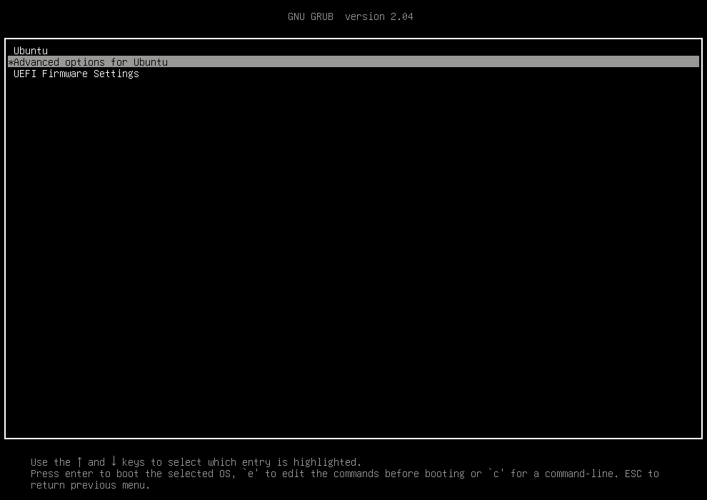
Press Esc immediately after the BIOS POST to enter the GRUB menu.
Select Advanced Options for Ubuntu and press Enter:
Select the latest 5.4 kernel version listed and press Enter to begin booting:
Log in and run a terminal again.
Check that the machine is actually running a 5.4 kernel version using the uname command: uname -r 5.4.0-81-generic
Install the Nvidia legacy driver: sudo apt install nvidia-340
If all goes well then you can remove the HWE kernel packages: sudo apt-get remove --purge linux-generic-hwe-20.04 linux-oem-20.04 linux-hwe-* linux-oem-* linux-modules-5.1*
Reboot and check that everything works!
So that’s not the most “direct” method, but it’s the least likely to get you into a frustrating position like accidentally removing all of the kernel packages entirely and rendering the machine unbootable.
If you want to verify the driver being used for the GPU, launch a terminal and run lspci to find the PCI address of the Nvidia GPU:
In this case we can see the GPU itself is at PCI address 03:00.0 although this may differ on your system. Run lspci in verbose mode (-v) and specify the address (-s 03:00.0) to find the kernel module (driver) in use:
lspci -vs 03:00.0
03:00.0 VGA compatible controller: NVIDIA Corporation GT218 [GeForce 210] (rev a2) (prog-if 00 [VGA controller])
	Subsystem: ASUSTeK Computer Inc. GT218 [GeForce 210]
	Flags: bus master, fast devsel, latency 0, IRQ 88
	Memory at f6000000 (32-bit, non-prefetchable) [size=16M]
	Memory at e0000000 (64-bit, prefetchable) [size=256M]
	Memory at f0000000 (64-bit, prefetchable) [size=32M]
	I/O ports at 8000 [size=128]
	Expansion ROM at 000c0000 [virtual] [disabled] [size=128K]
	Capabilities: <access denied>
	Kernel driver in use: nvidia
	Kernel modules: nvidiafb, nouveau, nvidia
In this case the driver in use is nvidia, which is the official Nvidia driver and should enable full hardware acceleration capabilities of the GPU.
If you do end up with a non-working system, press Esc at boot to get to the GRUB prompt and try booting into recovery mode. That should enable you to be able to remove the Nvidia driver package, reinstall the HWE kernel and revert any changes.
Last year I bought a Yamaha RX-V381 AV receiver to replace my ancient Pioneer one. I’m no big home theatre enthusiast – I just wanted a simple but solid surround receiver with some HDMI inputs so I could simplify the home setup. I’d previously had a set-top box, Kodi player (Raspberry Pi 2) and Chromecast all connected to the (getting oldish now) Samsung TV, and having to separately switch the video and audio signals was getting tedious.
For the price this amp simply rocks. Ample power, clean sound (discrete amp too), 5.1 speaker support, 4x HDMI inputs and the usual analogue ones plus it’s 4k compatible to boot.
The remote and UI is simple and uncluttered. Basically everything I wanted and nothing I didn’t
The best part is that HDMI CEC worked out of the box. It’s off by default but can be easily turned on in the amp’s HDMI settings menu.
The amp remote (and the TV one too – we can simply use the nearest one lying about) completely controls the Pi with Kodi, the STB and Chromecast without any fiddling. It’s very handy to say the least. The only drawback is the standby sync is a little odd, but this seems to be a common issue with CEC. There is some scope for tweaking it in the settings on each device though.
All was well for six months or so… until today. The CEC stopped working and no amount of power cycling or fiddling was going to get it back. Interestingly enough everything was powered on and had already been working – we simply left it for half an hour or so and came back to with no ability to remove control devices except from their respective original remotes.
Ultimately the WAF took a dive, prompting a pretty immediate fix!
In the end the amp was to blame and required a factory reset. To do this:
Power it off.
Hold down Straight while powering it back on until ADVANCED SETUP appears on the display.
Use the Program Selector buttons to navigate to INIT- CANCEL.
Press Straight to set it to INIT- ALL.
Press the power button again to reset the amp.
Unfortunately this meant re configuring all amp with all of my previous settings. If it happens again then a warranty claim is probably in order. A pity, as it’s otherwise such a great value little unit.
So anyway there’s a tip for anyone else who encounters this problem.
I now have on hand a Clarion/McIntosh PF-2824I and PF-4113I head units. These are fitted to higher end Subaru Legacy vehicles produced between 2005-2008. It includes MP3 and WMA support (why they didn’t support AAC instead of WMA beats me), a dual row VFD display and a more integrated look than the previous version (PF-2551I).
The PF-4113I is the Japanese version of the PF-2824I with a different tuner and a MiniDisc player. They are built around the same hardware platform (most components are the same including the PCB), however unfortunately run slightly different firmware. Unlike the previous model of McIntosh head unit in 2003-2005 Legacys, there is no easy way to convert the PF-4113I to European or American FM bands without hacking or replacing the firmware. There does appear to be a Micom firmware upgrade port on the side of the main board in the unit, however it appears that the microprocessor is of a mask ROM type and therefore cannot be flashed with new firmware.
It does use the same FM tuner module as many older McIntosh units, so if the firmware were to be sorted the necessary tuner mods are very simple.
Under the left hand seat is the EF-1259I amplifier. Unlike the old EF-1080I, this amplifier does not contain any EQ or crossover components as all this is now done in the head unit.
McIntosh Secret Key Combinations
After a bit of reading I’ve found that many Subaru head units have hidden options for changing settings. I couldn’t find much information on this unit so I spent a few moments trying various combinations to see what happens. Here’s the list I’ve discovered so far. If you discover any more please let everybody know by posting it in the comments!
To use these key combinations, switch the ignition to ACC and make sure the head unit is powered off.
Radio Location
Press the following to change the radio tuner region.
PF-2842I:
1 + AM is AUSTRALIA
2 + AM is EXPORT (North America)
5 + AM is AUS & EXP
Here are the differences between these modes:
Location
AM Range
AM Step
FM Range
FM Step
Australia
531–1620 kHz
9 kHz
87.5 – 108 MHz
100 kHz
Export
540–1610 kHz
5 kHz
87.5 – 107.9 MHz
100 kHz
Aus & Exp
Same as Australia
Note that switching locations will erase the radio presets.
PF-4113I:
5 + AM is JAPAN
Display firmware version
Press 5 + 6 + FM
Results:
PF-2824I (Japanese manufactured):
M 4.20
G34.72
PF-4113I:
M 5.60
G37.00 0.37
Disc 1 on the display lights in both cases too. If anyone has details for Chinese-manufactured versions of the radios please let me know.
Button and Display Test
5 + 6 + press RPT twice
Button test that displays the name of any button you push as well as the tuning up/ down.
Use the volume knob to toggle the display test feature which illuminates every display element and LED. When in display test you can use the tune knob to toggle a checker board pattern to more easily view display state. This will make any phosphor burn very obvious!
To exit this mode switch the ignition off.
Equaliser
In previous McIntosh models this was an analogue circuit built into the amp or head unit. It’s now all software controlled so can be changed between a number of presets or bypassed completely. This is very useful if you buy a replacement unit, so you can have it sound like the original if it needs to be replaced.
Press the following buttons and T/B:
1 + 3 + T/B WAGON CLOTH SEAT
1 + 4 + T/B SEDAN CLOTH SEAT
2 + 3 + T/B WAGON LEATHER SEAT
2 + 4 + T/B SEDAN LEATHER SEAT
2 + 5 + T/B THROUGH MODE (bypass)
I haven’t investigated the frequency response of each setting, however after a very quick listen the sedan options appear to have more bass than the wagon (quick bass boost option if you have a wagon!) and the cloth seat options appear to have a little treble boost. While it’s intended to compensate for the acoustics of the vehicle interior, purists might prefer to bypass the EQ altogether.
Loudness Control
Unlike the other settings, this must changed while the unit is powered on.
To toggle loudness, press 5 + 6 + T/B.
The default setting is on.
Other
Press 1 + 4 + CD to enter some sort of diagnostics mode. This displays the following:
H01 A1 256
Use tune to scroll through various options. As far as I can it seems to be read only. It also plays the current CD and the volume control works normally while in this mode.
Or at least it probably is. I can’t verify that, but it is really damn small!
I’ve based this around the VoCore, a tiny and inexpensive (US$20) Linux platform based around an Ralink RT5350F and running the fantastic OpenWRT.
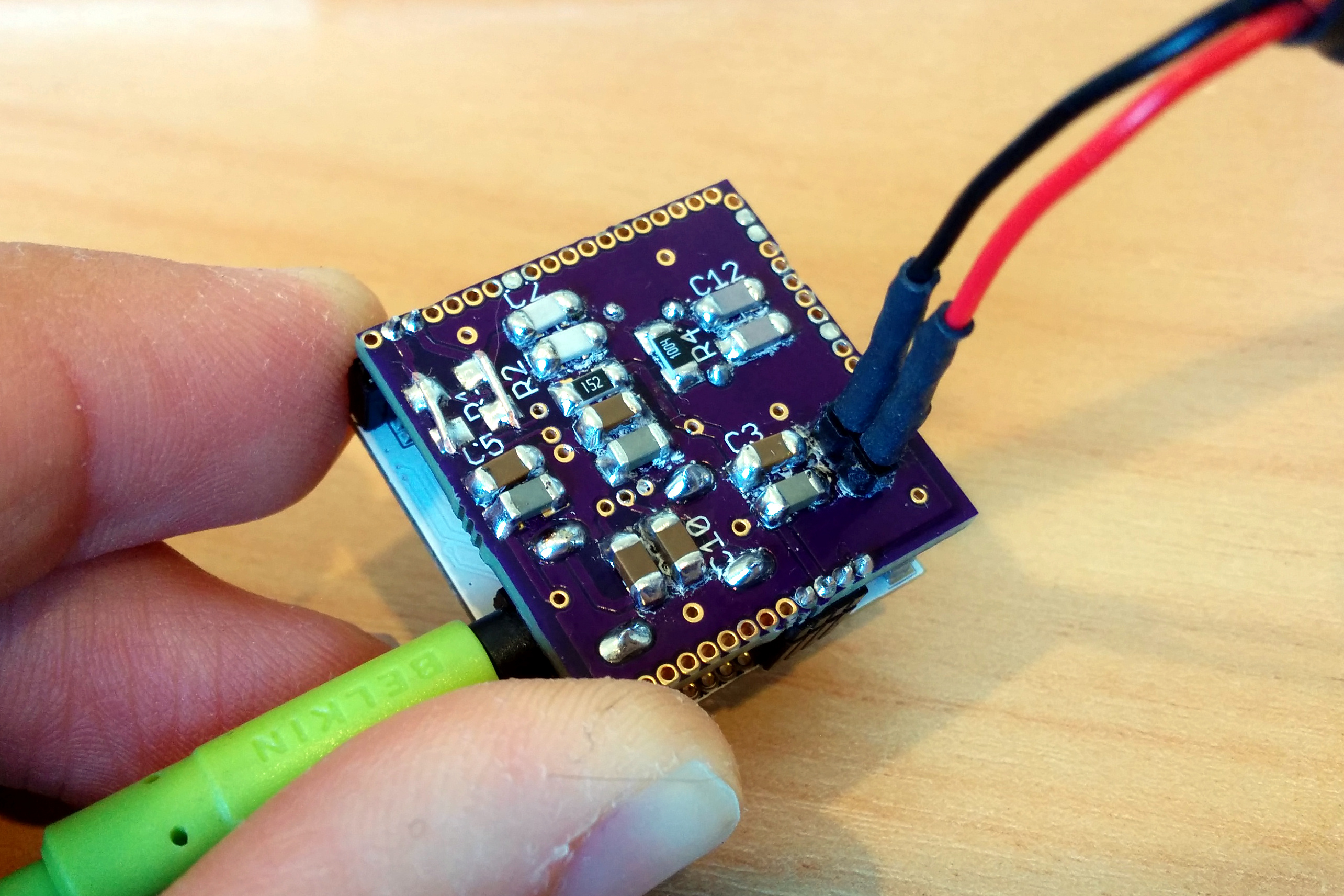
With my prototype audio dock the completed size is approx 25 x 25 x 10mm so can be made to fit almost anywhere. It could be easily integrated into an existing amplifier or set of powered speakers, enabling AirPlay-enablement of practically anything.
Prototype VoCore audio dock in action.
Setting up a new VoCore for AirPlay
First you will either need a VoCore dock and USB sound card or a VoCore audio dock. A USB to serial adapter is also a good idea as it makes life a lot easier if you make a mistake when configuring network settings.
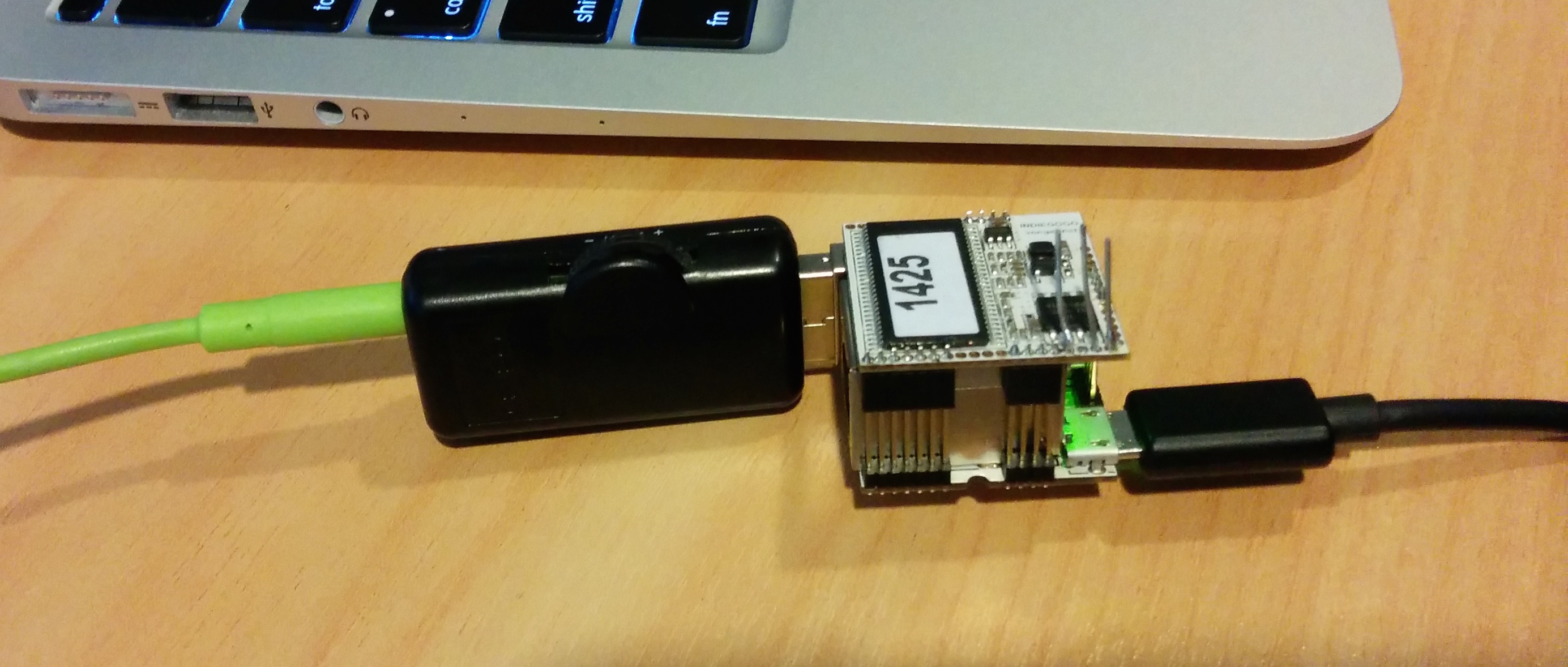
A word of warning: buy your USB sound adapter from a reputable source or manufacturer. Both myself and others I’ve spoken to have found those cheap generic $3 adapters all over eBay and dx.com to be of extremely poor quality and very unlikely to work.
First test using a low-cost USB audio adapter.
Set up networking
If you are using the official VoCore dock, simply plug in an Ethernet cable. If you are using the bare-bones VoCore, join the default WiFi network that it presents. Once that’s done you should be able to SSH into it.
First we need to set up networking so that the VoCore works as a client on your WiFi network. I expect that most folks won’t care about the Ethernet side, and even if you do it simply works out of the box so you don’t need to worry about this step!
Edit the /etc/config/wireless file and ensure it looks like this (remove any existing lines). Note that you will need to substitute your own SSID and passphrase:
Now edit /etc/config/network and add or update the following lines (leave everything else in place):
 config interface 'wwan'
    option proto 'dhcp'
Reboot the VoCore and it should associate itself with your WiFi network.
Update the firmware
While we can compile a custom OpenWRT build, that’s better suited if we need to add custom hardware support (such as VIA audio support in the HP thin terminal). There’s very little point with the VoCore as the standard Barrier Breaker image works really well for ShairPlay on the VoCore. On your VoCore’s terminal run the following:
cd /tmp
wget http://downloads.openwrt.org/barrier_breaker/14.07/ramips/rt305x/openwrt-ramips-rt305x-vocore-squashfs-sysupgrade.bin
Check that the image file isn’t damaged:
wget http://downloads.openwrt.org/barrier_breaker/14.07/ramips/rt305x/md5sums
md5sum -c md5sums 2> /dev/null | grep OK
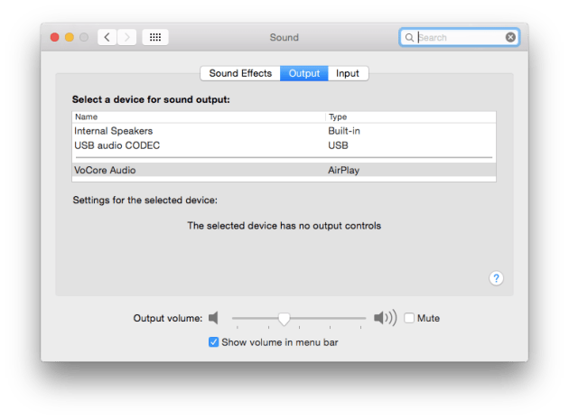
While the defaults for ShairPort work fine, we should at least set a suitable name for the AirPlay server to announce itself as by editing the following line in /etc/config/shairport:
option bname 'VoCore Audio'
That’s it! Reboot the VoCore and it should soon appear as an output device in OS X or iOS:
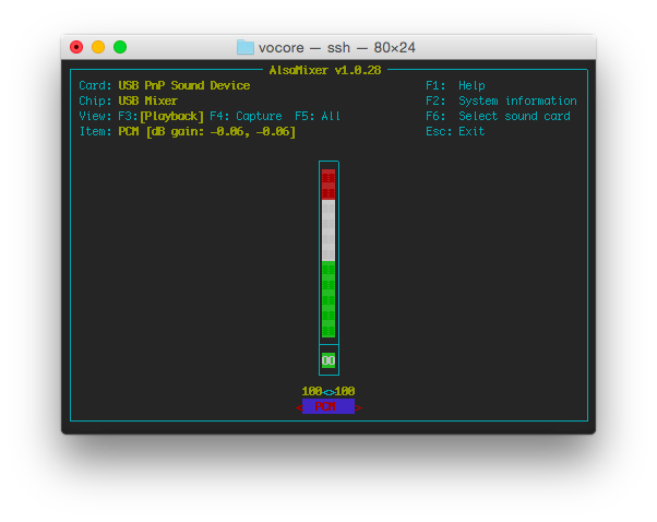
If you have trouble getting audio to work, run alsamixer on the VoCore and check that the PCM volume is set adequately:
Failing that, use dmesg to confirm that the USB audio device is detected properly:
[   17.550000] snd-usb-audio 2-1:1.0: no of_node; not parsing pinctrl DT
[   17.610000] usbcore: registered new interface driver snd-usb-audio
Want a nice tidy platform for running Ubiquiti’s UniFi controller as a stand-alone appliance? Here’s a tidy solution using an HP t5570e thin client.
Background
I recently became involved with a local school who had terrible trouble with their wireless infrastructure. The school is quite small and had a number of first-generation Apple Airport Express access points. Someone has also added a Linksys unit of some description and things were generally pretty flakey. Another local firm had replaced some of the access points with some cheap D-Link ones (Realtek-based) and from there things got even worse (surprise!).
After a little research I implemented two fixes and now things are rock solid:
Replaced a faulty Allied Telesyn Ethernet switch. While it appeared to work at a glance it had a bad habit of randomly dropping frames. Sadly my experience with ATI over the years has not been good and this certainly didn’t help.
Replaced all of the access points with Ubiquiti’s UniFi series.
Now I have no ties to Ubiquiti – I’ve just had a lot of success with their products over the last eight years or so. The UniFi platform is quite interesting as it requires a controller server in order to manage it, log stats and generally provide additional functionality. The trouble is that the school only had one desktop computer and the server is simply a Synology NAS appliance (these are also very good products I might add).
The desktop ran Windows 7 and was used by the office assistant. I installed UniFi on this as it was the only realistic option available at the time, but after a month or so it was clear that this would not suffice. It didn’t support running as a service without a bit of mucking around, and it had a tendancy to hog enough memory to cause a noticeable performance impact to the staff using it. Not only that, staff often needed reminding not to switch the machine off.
I had a look at various low-cost embedded options including the Raspberry Pi and ALIX boards. Most were slow and in many cases weren’t that cheap particularly once a case, storage and power supply were added.
In the end I found a new HP t5570e thin client going very cheap (NZ$90) and gave it a shot. It’s been running a a few months now and has never skipped a beat. It currently manages a network of about six access points and up to 40 clients, and looks to have enough capacity to grow further. The load average sits less than 0.1, memory typically around 60% usage and only 1.3GB disk space has been used.
HP t5570e thin client
This is just a small form factor PC that includes the following specs (full PDF here):
VIA Nano u3500 1GHz CPU
2GB RAM
4GB IDE SSD (upgraded to an 8GB SSD so that Mongo can journal properly)
Gigabit Ethernet
Best of all there’s no moving bits like fans and hard disks to worry about.
I opted to install Voyage Linux 0.9.6 due to the fact it’s built on Debian Wheezy and has a nice small footprint, optimised for installing on small flash storage.
Voyage Linux Installation
Here’s how to get Voyage onto the thin client.
Download the Voyage live CD image from http://linux.voyage.hk/download. The Nano is an x86-64 CPU so grab the amd64 version.
Copy the ISO image to a USB stick. In Mac OS X this is done as follows (assuming disk1 is the USB stick device — check with diskutil list). If you use Ubuntu jst use the startup disk creator. In Windows, try XBOOT.
Insert the USB stick into the HP thin terminal, along with a keyboard and display. Power it on and wait for it to boot, then follow the steps below. The default login is root with the password voyage. Note the steps to perform in bold. In most cases the defaults are acceptable.
Linux voyage 3.10.11-voyage #1 SMP Fri Dec 6 17:15:44 HKT 2013 x86_64
The programs included with the Debian GNU/Linux system are free software;
the exact distribution terms for each program are described in the
individual files in /usr/share/doc/*/copyright.
Debian GNU/Linux comes with ABSOLUTELY NO WARRANTY, to the extent
permitted by applicable law.
__  __
\ \/ /___ __  __ ___  ___  ___    Useful Commands:
 \  // _ \\ \/ /,-_ |/ _ |/ -_)     remountrw - mount disk as read-write
  \/ \___/ \  / \___,\_  |\___|     remountro - mount disk as read-only
          _/_/        _'_|          remove.docs - remove all docs and manpages
    { V o y a g e } - L i n u x
     < http://linux.voyage.hk >   Version: 0.9.2 (Build Date 20131219)
root@voyage:~# mkdir /tmp/root
root@voyage:/tmp/root#  mkdir /tmp/ide
root@voyage:~# mount -o loop /lib/live/mount/medium/live/filesystem.squashfs /tmp/root
root@voyage:~# cd /tmp/root
root@voyage:/tmp/root# /usr/local/sbin/voyage.update
What would you like to do?
 1 - Create new Voyage Linux disk
 2 - Update existing Voyage configuration
 3 - Exit
     (default=1 [Create new Voyage Linux disk]):
some mandatory options are unset, please enter them interactively
Where is the Voyage Linux distribution directory?
 (default=/tmp/root):
What would you like to do?
 1 - Specify Distribution Directory
 2 - Select Target Profile - this overwrites current settings
 3 - Select Target Disk
 4 - Select Target Bootstrap Loader
 5 - Configure Target Console
 6 - Partition and Create Filesystem
     (default=2 [Select Target Profile - this overwrites current settings]):
Please select Voyage profile:
 1 - Keep existing settings
 2 - 4501
 3 - 4511/4521
 4 - 4801
 5 - 5501
 6 - 6501
 7 - ALIX
 8 - APU
 9 - Generic PC
 10 - Notebook (pcmcia)
 11 - WRAP
     (default=7 [ALIX]): 9
What would you like to do?
 1 - Specify Distribution Directory
 2 - Select Target Profile - this overwrites current settings
 3 - Select Target Disk
 4 - Select Target Bootstrap Loader
 5 - Configure Target Console
 6 - Partition and Create Filesystem
     (default=3 [Select Target Disk]):
Partitions information
major minor  #blocks  name
  8        0    2000376 sda
  8        1    2000092 sda1
  8       16    7816704 sdb
  8       17      62432 sdb1
  7        0      51244 loop0
  7        1      51244 loop1
Which device accesses the target disk [/dev/hde]? /dev/sda
Which partition should I use on /dev/sda for the Voyage system [1]?
Device information for /dev/sda1
device     fs_type label    mount point    UUID
-------------------------------------------------------------------------------
/dev/sda1  ext2    VOYAGE_FS (not mounted) ed3c0453-149d-4a96-a6d9-5f523e21b0ca
Where can I mount the target disk [/tmp/ide]?
What would you like to do?
 1 - Specify Distribution Directory
 2 - Select Target Profile - this overwrites current settings
 3 - Select Target Disk
 4 - Select Target Bootstrap Loader
 5 - Configure Target Console
 6 - Partition and Create Filesystem
     (default=4 [Select Target Bootstrap Loader]):
Which loader do you want (grub or lilo) [grub]?
Which partition is used for bootstrap [1]?
What would you like to do?
 1 - Specify Distribution Directory
 2 - Select Target Profile - this overwrites current settings
 3 - Select Target Disk
 4 - Select Target Bootstrap Loader
 5 - Configure Target Console
 6 - Partition and Create Filesystem
     (default=5 [Configure Target Console]):
Select terminal type:
 1 - Serial Terminal
 2 - Console Interface
     (default=2 [Console Interface]):
What would you like to do?
 1 - Specify Distribution Directory
 2 - Select Target Profile - this overwrites current settings
 3 - Select Target Disk
 4 - Select Target Bootstrap Loader
 5 - Configure Target Console
 6 - Partition and Create Filesystem
     (default=6 [Partition and Create Filesystem]):
What shall I do with your Flash Media?
 1 - Partition Flash Media and Create Filesystem
 2 - Use Flash Media as-is
     (default=1 [Partition Flash Media and Create Filesystem]):
What would you like to do?
 1 - Specify Distribution Directory
 2 - Select Target Profile - this overwrites current settings
 3 - Select Target Disk
 4 - Select Target Bootstrap Loader
 5 - Configure Target Console
 6 - Partition and Create Filesystem
     (default=7 [Copy Distribution to Target]):
Configuration details:
----------------------
Distribution directory:   /tmp/root
Disk/Flash Device:        /dev/sda
Installation Partition:   /dev/sda1
Create Partition and FS:  yes
Bootstrap Partition:      /dev/sda1
Will be mounted on:       /tmp/ide
Target system profile:    Generic PC
Target console:           standard
Bootstrap installer:      grub
Bootstrap partition:      /dev/sda1
OK to continue (y/n)? y
Ready to go ....
Checking that no-one is using this disk right now ...
OK
Disk /dev/sda: 249 cylinders, 255 heads, 63 sectors/track
Old situation:
Units = cylinders of 8225280 bytes, blocks of 1024 bytes, counting from 0
  Device Boot Start     End   #cyls    #blocks   Id  System
/dev/sda1   *      0+    248     249-   2000092   83  Linux
/dev/sda2          0       -       0          0    0  Empty
/dev/sda3          0       -       0          0    0  Empty
/dev/sda4          0       -       0          0    0  Empty
New situation:
Units = cylinders of 8225280 bytes, blocks of 1024 bytes, counting from 0
  Device Boot Start     End   #cyls    #blocks   Id  System
/dev/sda1   *      0+    248     249-   2000092   83  Linux
/dev/sda2          0       -       0          0    0  Empty
/dev/sda3          0       -       0          0    0  Empty
/dev/sda4          0       -       0          0    0  Empty
Successfully wrote the new partition table
Re-reading the partition table ...
If you created or changed a DOS partition, /dev/foo7, say, then use dd(1)
to zero the first 512 bytes:  dd if=/dev/zero of=/dev/foo7 bs=512 count=1
(See fdisk(8).)
mke2fs 1.42.5 (29-Jul-2012)
Filesystem label=
OS type: Linux
Block size=4096 (log=2)
Fragment size=4096 (log=2)
Stride=0 blocks, Stripe width=0 blocks
125184 inodes, 500023 blocks
25001 blocks (5.00%) reserved for the super user
First data block=0
Maximum filesystem blocks=515899392
16 block groups
32768 blocks per group, 32768 fragments per group
7824 inodes per group
Superblock backups stored on blocks:
   32768, 98304, 163840, 229376, 294912
Allocating group tables: done
Writing inode tables: done
Writing superblocks and filesystem accounting information: done
tune2fs 1.42.5 (29-Jul-2012)
Setting maximal mount count to -1
Setting interval between checks to 0 seconds
Copying files .... done
Removing pcmcia from update-rc.d
perl: warning: Setting locale failed.
perl: warning: Please check that your locale settings:
   LANGUAGE = (unset),
   LC_ALL = (unset),
   LANG = "en_NZ.UTF-8"
    are supported and installed on your system.
perl: warning: Falling back to the standard locale ("C").
update-rc.d: using dependency based boot sequencing
Removing dnsmasq.pxe.conf in /etc/dnsmasq.more.conf
Reconfiguring resolvconf
perl: warning: Setting locale failed.
perl: warning: Please check that your locale settings:
   LANGUAGE = (unset),
   LC_ALL = (unset),
   LANG = "en_NZ.UTF-8"
    are supported and installed on your system.
perl: warning: Falling back to the standard locale ("C").
perl: warning: Setting locale failed.
perl: warning: Please check that your locale settings:
   LANGUAGE = (unset),
   LC_ALL = (unset),
   LANG = "en_NZ.UTF-8"
    are supported and installed on your system.
perl: warning: Falling back to the standard locale ("C").
Updating /etc/hosts
Installing grub
Copy grub files from /tmp/ide to /tmp/ide/boot/grub
Setting up grub under chroot /tmp/ide
copyfiles.sh script completed
What would you like to do?
 1 - Specify Distribution Directory
 2 - Select Target Profile - this overwrites current settings
 3 - Select Target Disk
 4 - Select Target Bootstrap Loader
 5 - Configure Target Console
 6 - Partition and Create Filesystem
     (default=8 [Exit]):
root@voyage:/tmp/root# reboot
Remove the Voyage USB stick when prompted.
Post-Installation Tasks and UniFi Installation
Once the thin terminal has booted into Voyage there are a few more installation steps required.
First set a new root password:
passwd
Set a hostname:
echo unifi > /etc/hostname
Set APT to use NZ (or your local country) repository mirrors instead of Japanese ones to speed up downloads:
sed -i -e 's/ftp.jp.debian.org/ftp.nz.debian.org/g' /etc/apt/sources.list
Update the repository cache and install security patches:
apt-get update
apt-get upgrade
Fix locales:
apt-get install locales
dpkg-reconfigure locales
Install required locales (e.g. 131) and select as system default.
Uninstall some network services we don’t need to free up disk space and improve security:
If you are using a HDD or SSD smaller than 16GB you will need to disable journaling in the UniFi database to save disk space. Note that this could increase the chances of DB corruption after dirty shutdowns.
service unifi stop
service mongodb stop
echo "unifi.db.nojournal=true" >> /var/lib/unifi/system.properties
service mongodb start
service unifi start
Add ACPI power button support so that staff can easily shut down the server properly if required. This is optional but recommended:
apt-get install acpid
echo -e 'event=button/power (PWR.||PBTN)\naction=/sbin/shutdown -h now "Power button pressed"' > /etc/acpi/events/power
service acpid restart
From here you should be able to browse to the UniFi web interface (it should appear at https://unifi:8443) and get started setting up access points.
Some users may wish to assign a static IP address to the UniFi controller too – I felt this unnecessary and in practice it doesn’t seem to matter.


 I recently became involved with a local school who had terrible trouble with their wireless infrastructure. The school is quite small and had a number of first-generation Apple Airport Express access points. Someone has also added a Linksys unit of some description and things were generally pretty flakey. Another local firm had replaced some of the access points with some cheap D-Link ones (Realtek-based) and from there things got even worse (surprise!).
